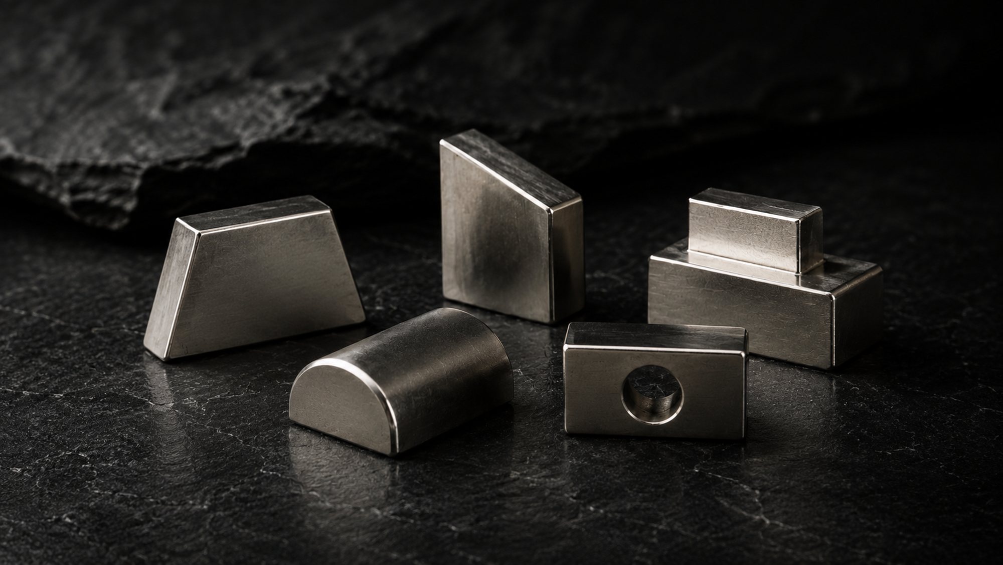
sintered NdFeB
Irregular & Custom Shapes
Machined-to-drawing NdFeB: geometry you can actually make
Sintered NdFeB parts ground, sliced or wire-EDM'd to a customer drawing rather than to a catalogue shape — trapezoids, wedges, bread-loaf profiles, stepped blocks and one-off geometry. Choose this route when the airgap profile or the packaging envelope dictates the shape and a stock block would force a compromise in the magnetic circuit. The penalty is cost and yield: complex geometry means multiple grinding setups, significant material loss to swarf, and edges that are structurally fragile in a brittle material.
Request a quoteSpecification
- Grade range
- N35-N52; M, H, SH, UH, EH temperature classes (N35M-N48M, N33H-N45H, N30SH-N45SH, N28UH-N40UH, N28EH-N38EH). Highest BHmax and highest temperature class are mutually exclusive — coercivity additions cost remanence.
- BHmax
- 263-414 kJ/m3 (33-52 MGOe), grade dependent; EH classes sit at the low end (roughly 210-300 kJ/m3, 28-38 MGOe)
- Max operating temperature
- 80 C (N) to 200 C (EH) — indicative only, and quoted at a favourable permeance coefficient. Actual limit is set by permeance coefficient and demagnetising field, not by the grade letter. Thin-in-the-pole-direction wedges lose margin fast and can fall well short of the catalogue figure.
- Tolerance
- As-sintered +/-0.1 mm on small features; ground faces +/-0.05 mm standard, +/-0.02 mm achievable on selected dimensions; angles +/-0.5 deg standard, +/-0.17 deg (10 arcmin) on request; arc/bread-loaf profile +/-0.05 mm to template
- Coatings
- Sintered NdFeB always requires a coating — it corrodes readily bare. NiCuNi (10-20 um), Zn (5-10 um), epoxy (15-25 um), NiCuNi+epoxy duplex, Ni+Au, phosphate (interim protection only, not a service coating). Complex geometry favours epoxy or duplex over bright nickel.
- Size range
- Roughly 2 mm to 100 mm across the largest face; pole-direction thickness 0.8 mm minimum on simple sections, 1.5 mm practical minimum where the face is angled or stepped. Larger parts are segmented and bonded.
- Magnetisation
- Through-thickness, through-width, or through-length, parallel to a nominated datum face. Orientation is set at pressing and does not follow curved or tapered geometry. Multipole and radial orientation require dedicated tooling.
- Typical lead time
- First articles 15-25 days from drawing sign-off using existing blanks and machining; 30-45 days where a new near-net pressing die is required
Typical applications
- Motor rotors using arc-segment or bread-loaf poles where a shaped airgap profile reduces cogging torque and THD in back-EMF
- Halbach arrays and linear motors requiring trapezoidal or wedge blocks that tile into a closed ring or track with minimal gaps
- Magnetic couplings and eddy-current brakes where wedge segments fill an annular pocket more efficiently than rectangles
- Sensor and encoder assemblies needing stepped or chamfered poles to shape field gradient over a Hall or TMR device
- Loudspeaker and actuator motors where non-round pole geometry sets the flux distribution in a narrow gap
- Magnetic separators and holding fixtures where parts are machined to a customer drawing to sit flush in a housing
Engineering notes
- Machining cost dominates, not material cost. Sintered NdFeB is only workable by grinding, wire EDM and slicing — it cannot be turned or milled. Every non-rectangular face is a separate grinding or EDM setup, so a trapezoid with two angled faces can cost 2-4x a rectangular block of the same mass. Where volume justifies it, a pressing die that gets closer to net shape usually pays back above roughly 5,000-10,000 pieces.
- Material utilisation on wedges and bread-loaf profiles is typically 40-65% of the pressed blank. That swarf is not recoverable at full value, so quoted piece price carries the waste. If your geometry can tolerate it, ask whether a simpler shape plus a machined steel pole piece gives the same field for less money.
- Orientation is fixed at pressing and cannot follow a curved or angled face. A bread-loaf magnet oriented parallel through its thickness has a genuinely uniform direction; the curved surface only shapes the airgap, it does not bend the flux. Radially oriented arcs are a different and more expensive tool. If your FEA assumes radial orientation, say so explicitly on the RFQ — the difference is not cosmetic.
- Corners and thin sections are the failure mode. Sintered NdFeB has roughly 250-350 MPa flexural (transverse rupture) strength, near-zero ductility and chips readily. Included angles below about 20-25 deg, knife edges and wall sections under about 1.0-1.5 mm push yield down and scrap up. Specify a 0.2-0.5 mm chamfer or radius on every exposed edge unless there is a functional reason not to — it costs little and it is the single biggest lever on handling and assembly damage.
- Coating on a complex shape is not uniform. Electroplated NiCuNi builds up on convex edges and thins in re-entrant corners and slots; blind holes and internal steps may plate thin or not at all. For stepped or slotted parts, epoxy or a NiCuNi + epoxy duplex is usually the more honest choice, and you should expect coating thickness to be specified as a minimum rather than a nominal.
Magnetic properties
Sintered NdFeB grade data
Measured at 20 °C. Every shipment leaves with a hysteresigraph report against these figures — ask for the lot data, not a datasheet reprint.
| Grade | Br (T) | Hcb (kA/m) | Hcj (kA/m) | BHmax (kJ/m³) | BHmax (MGOe) | Max op. temp. |
|---|---|---|---|---|---|---|
| N35 | 1.17–1.22 | ≥ 868 | ≥ 955 | 263–287 | 33–36 | 80 °C |
| N38 | 1.22–1.25 | ≥ 899 | ≥ 955 | 287–310 | 36–39 | 80 °C |
| N42 | 1.28–1.32 | ≥ 923 | ≥ 955 | 318–342 | 40–43 | 80 °C |
| N45 | 1.32–1.38 | ≥ 923 | ≥ 955 | 342–366 | 43–46 | 80 °C |
| N48 | 1.38–1.42 | ≥ 923 | ≥ 876 | 366–390 | 46–49 | 80 °C |
| N52 | 1.43–1.48 | ≥ 876 | ≥ 876 | 398–422 | 50–53 | 80 °C |
| N42M | 1.28–1.32 | ≥ 963 | ≥ 1114 | 318–342 | 40–43 | 100 °C |
| N42H | 1.28–1.32 | ≥ 963 | ≥ 1353 | 318–342 | 40–43 | 120 °C |
| N42SH | 1.28–1.32 | ≥ 979 | ≥ 1592 | 318–342 | 40–43 | 150 °C |
| N38UH | 1.22–1.25 | ≥ 923 | ≥ 1990 | 287–310 | 36–39 | 180 °C |
| N35EH | 1.17–1.22 | ≥ 876 | ≥ 2388 | 263–287 | 33–36 | 200 °C |
Read the suffix, not just the number. None / M / H / SH / UH / EH denote intrinsic coercivity class — higher classes hold their magnetism hotter, at the cost of remanence and heavy rare earth (Dy/Tb). Max operating temperatures assume a permeance coefficient near 2: a thin magnet, or one facing an opposing coil field, will lose output well below the figure quoted. Figures are typical production ranges, not guaranteed minima for every lot.
Answers
Irregular & Custom Shapes FAQ
Can you work from a 2D PDF, or do you need a 3D model?
A dimensioned 2D drawing is workable and is what most quotes are built from, but it must show the magnetisation direction with an arrow, the tolerance on each feature (not just a blanket general tolerance), the coating and its minimum thickness, and which surfaces are functional. A STEP file alongside it removes ambiguity on angled and curved faces and speeds up quoting. What we cannot infer from geometry alone is orientation direction and which dimension is critical — those two omissions cause most RFQ back-and-forth.
Why is my wedge quoted at several times the price of a block of the same weight?
Two reasons, and both are physical rather than commercial. First, the wedge is ground out of a rectangular pressed blank, so you are paying for the material that becomes swarf — typically 35-60% of it. Second, each angled or curved face needs its own fixturing and grinding pass. Cost tracks setups and removed volume, not finished mass. If the shape is stable and volumes are real, a near-net pressing die (tooling cost in the low thousands of USD, several weeks lead) moves both numbers substantially.
Should the part be magnetised before or after you machine it?
After, in nearly all cases. Machining a magnetised part means grinding swarf clings to the workpiece and the wheel, dimensional control suffers and the coating line becomes impractical. Standard flow is press and sinter, machine to drawing, coat, then magnetise — often after we have assembled it into your housing if you supply one. If you need magnetised loose parts, expect packaging and the air transport declaration for Class 9 magnetised material (UN 2807) to add cost and lead time. Note that the shipping trigger is a measured field limit at a set distance from the finished package, not a part size — a small high-grade magnet can fail where a larger weak one passes, so pack design and shielding matter more than part dimensions. Send us the pack configuration, not just the part drawing, if air freight is in scope.
Next