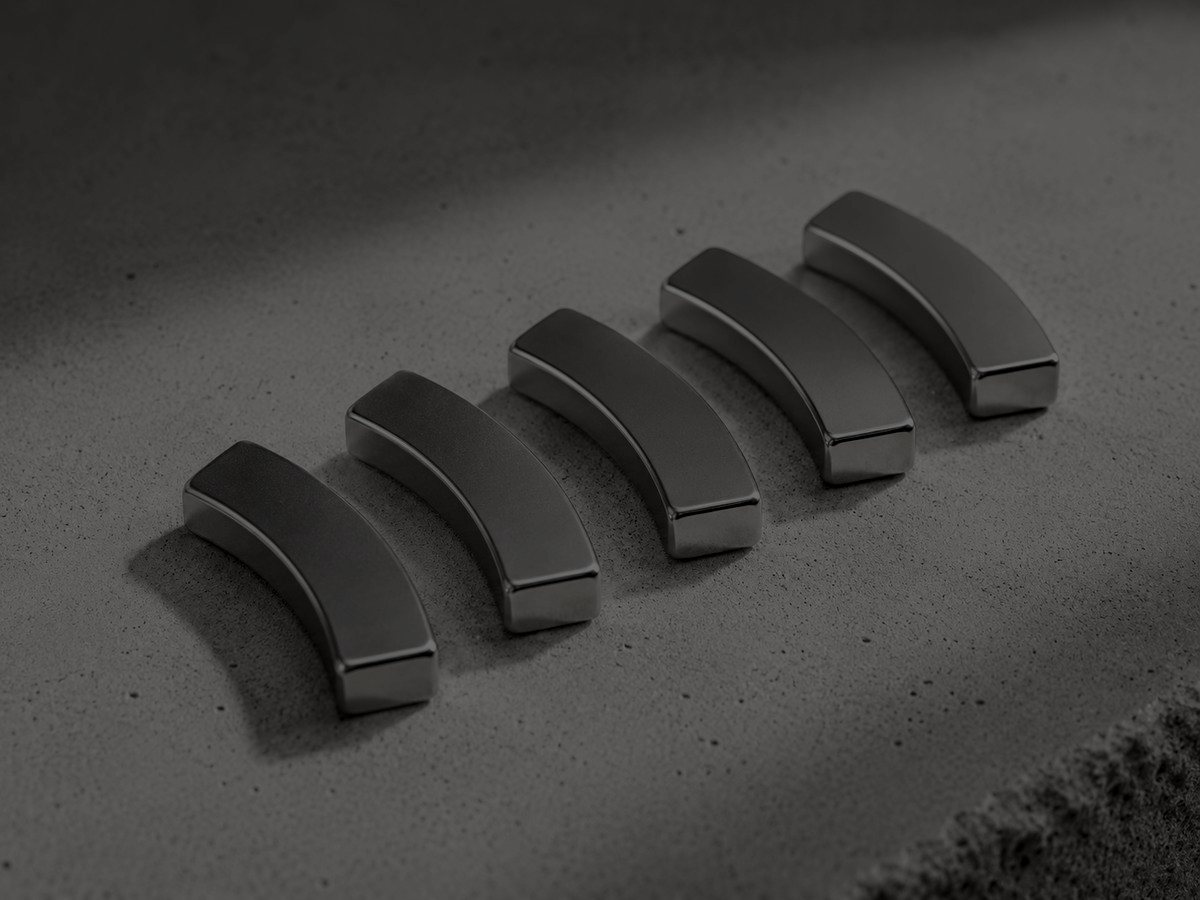
sintered NdFeB
Arc Segment Magnets
Arc segments for rotor surfaces, cut and ground to fit
Sintered NdFeB tiles with concentric inner and outer radii, used on surface-mounted PM rotors where the magnet must sit flush against a cylindrical yoke. Choose arc segments over blocks when you need a uniform working airgap across the pole and want to control the flux distribution through arc angle and radial thickness rather than accepting the flat-chord losses of a rectangular magnet. Geometry is defined by OR, IR, included angle, axial length and magnetisation direction — radial gives flux normal to the pole face and a flatter, more trapezoidal airgap distribution; parallel softens the profile toward sinusoidal and costs less in tooling on small parts.
Request a quoteSpecification
- Grade range
- N35–N52 (no coercivity suffix), N33M–N48M, N30H–N45H, N30SH–N42SH, N28UH–N38UH, N28EH–N35EH, N28AH–N33AH
- BHmax
- 263–414 kJ/m³ (33–52 MGOe) depending on grade; N42SH ≈ 318–342 kJ/m³, N35EH ≈ 263–287 kJ/m³
- Max operating temperature
- 60 °C (N50–N52), 80 °C (N35–N48), 100 °C (M), 120 °C (H), 150 °C (SH), 180 °C (UH), 200 °C (EH), up to 230 °C (AH). Quoted figures assume a healthy load line (Pc ≥ 2); a thin arc with a large airgap will demote in practice — see notes
- Intrinsic coercivity (Hcj)
- ≥955 kA/m (12 kOe) for N35–N48, ≥876 kA/m (11 kOe) for N50–N52; ≥1114 kA/m (M), ≥1353 (H), ≥1592 (SH), ≥1990 (UH), ≥2388 (EH), ≥2707 (AH)
- Dimensional tolerance
- Standard ±0.05 mm on OR/IR/length; ±0.02–0.03 mm achievable on ground faces at added cost (as-sintered surfaces are much looser — arcs are always ground). Arc angle ±0.5°; concentricity of IR to OR typically 0.05 mm TIR
- Size range
- OR 5–150 mm, radial wall 1.5–25 mm, arc angle 10–180°, axial length 2–60 mm as one piece (longer stacks assembled from segments)
- Magnetisation
- Radial (true radial via dedicated orientation fixture), parallel (uniform direction across the chord), or multipole on a single ring segment. Radial requires a die/orientation fixture — expect NRE and 3–5 weeks lead on first article
- Coatings
- NiCuNi (10–20 µm, default), Zn (5–15 µm), epoxy (15–25 µm), Ni+epoxy, Parylene C (5–15 µm), Everlube. NdFeB always requires a coating — the alloy corrodes readily. Salt-spray 48–96 h typical for NiCuNi; epoxy preferred where the arc will be bonded
Typical applications
- Surface-mounted PMSM and BLDC rotors — servo, spindle, fan and pump drives
- Automotive auxiliaries: EPS, e-compressor, cooling fan, brake actuators
- Permanent-magnet DC brushed motors (stator arcs bonded inside a steel can)
- Smaller direct-drive and generator rotors (note: large-diameter wind and hydro machines more often use rectangular blocks on segmented poles, where chord error is negligible and material utilisation is far better)
- Magnetic couplings and eddy-current brakes, where torque scales roughly with pole face area and airgap flux density
- Voice-coil and linear actuators using shallow, wide-angle segments
Engineering notes
- Arcs are the most fracture-prone NdFeB geometry we make. Sintered NdFeB is a brittle intermetallic alloy — around 250 MPa flexural strength and a fracture toughness of only about 2 MPa·m½ — so a thin-walled, wide-angle tile concentrates stress at the corners and edges. Chipping during coating, handling and rotor assembly is the dominant yield loss, not magnetic underperformance. Specify generous edge chamfers (0.3–0.5 mm) and expect to design a bonding fixture that never point-loads a corner.
- Radial magnetisation is not free. True radial orientation needs a press die with a curved cavity and a matched magnetising fixture, so first-article tooling adds cost and lead time. Below roughly 30–40 mm OR, parallel orientation across the chord is usually good enough — the chord and the arc barely differ — and lets you use standard tooling. Worth modelling before you commit to radial.
- Corners and edges of an arc see the lowest permeance in the part. The catalogue max operating temperature assumes a healthy load line; a 2 mm wall over a large airgap can reach its knee 30–50 °C below the quoted figure, and demagnetisation shows up first at the trailing edge under inverter fault current. Size grade from your FEA load line and worst-case short-circuit, not from the datasheet number. Note also that N50–N52 trade coercivity for remanence: they carry a lower Hcj floor and a ~60 °C rating, so the top of the N range is rarely the right choice for a thin arc.
- Coating adds real material to a curved surface and it is not uniform. Electroplated NiCuNi follows current density, so it builds up on the edges, corners and the convex OR, and thins in the concave IR and any recess — plan for the thick spots at the edges, not a pool in the IR. If your IR-to-yoke bondline or your OR airgap is critical, either grind after plating or budget for the coating in the stack-up. Epoxy is more forgiving for bonded joints but softer and easier to damage in assembly.
- Segments are made by cutting from a sintered block or by pressing near-net and grinding — either way you pay for material you throw away. Wide arcs from small blanks have poor material utilisation, and heavy-rare-earth grades (SH and above) make that waste expensive. Splitting a 180° pole into two 90° tiles is often cheaper and mechanically safer than one wide segment, at the cost of an extra joint line in the flux.
Magnetic properties
Sintered NdFeB grade data
Measured at 20 °C. Every shipment leaves with a hysteresigraph report against these figures — ask for the lot data, not a datasheet reprint.
| Grade | Br (T) | Hcb (kA/m) | Hcj (kA/m) | BHmax (kJ/m³) | BHmax (MGOe) | Max op. temp. |
|---|---|---|---|---|---|---|
| N35 | 1.17–1.22 | ≥ 868 | ≥ 955 | 263–287 | 33–36 | 80 °C |
| N38 | 1.22–1.25 | ≥ 899 | ≥ 955 | 287–310 | 36–39 | 80 °C |
| N42 | 1.28–1.32 | ≥ 923 | ≥ 955 | 318–342 | 40–43 | 80 °C |
| N45 | 1.32–1.38 | ≥ 923 | ≥ 955 | 342–366 | 43–46 | 80 °C |
| N48 | 1.38–1.42 | ≥ 923 | ≥ 876 | 366–390 | 46–49 | 80 °C |
| N52 | 1.43–1.48 | ≥ 876 | ≥ 876 | 398–422 | 50–53 | 80 °C |
| N42M | 1.28–1.32 | ≥ 963 | ≥ 1114 | 318–342 | 40–43 | 100 °C |
| N42H | 1.28–1.32 | ≥ 963 | ≥ 1353 | 318–342 | 40–43 | 120 °C |
| N42SH | 1.28–1.32 | ≥ 979 | ≥ 1592 | 318–342 | 40–43 | 150 °C |
| N38UH | 1.22–1.25 | ≥ 923 | ≥ 1990 | 287–310 | 36–39 | 180 °C |
| N35EH | 1.17–1.22 | ≥ 876 | ≥ 2388 | 263–287 | 33–36 | 200 °C |
Read the suffix, not just the number. None / M / H / SH / UH / EH denote intrinsic coercivity class — higher classes hold their magnetism hotter, at the cost of remanence and heavy rare earth (Dy/Tb). Max operating temperatures assume a permeance coefficient near 2: a thin magnet, or one facing an opposing coil field, will lose output well below the figure quoted. Figures are typical production ranges, not guaranteed minima for every lot.
Answers
Arc Segment Magnets FAQ
Radial or parallel magnetisation — how do I choose?
Radial puts flux normal to the pole face everywhere, which gives a flatter, more trapezoidal airgap distribution — generally what you want for six-step BLDC commutation. Parallel orients the whole tile in one direction across the chord, so toward the edges the flux leaves at an angle; that rounds the shoulders of the waveform and pushes it toward sinusoidal, which is often the better fit for a sine-driven PMSM chasing low back-EMF THD. As a rule of thumb, at small radii and up to roughly 60° arc angle the chord and the arc barely differ, so parallel is fine and cheaper. Above that the two orientations diverge and the choice should come out of your FEA, not a rule of thumb. Note that cogging torque is set mainly by slot/pole combination, skew and pole-arc ratio — do not expect orientation alone to fix it. Send your OR, IR, angle and target back-EMF waveform and this can be checked against the load line.
What tolerance should I actually specify?
±0.05 mm on OR, IR and length is standard and covers most rotor builds. Ask for ±0.02–0.03 mm only on the faces that set your airgap — usually the OR — because tightening every dimension multiplies grinding passes and cost. Arc angle at ±0.5° is rarely the binding constraint; concentricity between IR and OR matters more, since that is what determines whether the tile sits flat on the yoke or rocks. Remember the plating sits on top of the ground dimension unless you grind after coating. State which surface is the datum on your drawing.
Can you supply arcs already magnetised, or should we magnetise after assembly?
Both are possible, but magnetised arcs are difficult and hazardous to handle, ship and assemble — they snap together, chip, and pinch fingers. For most rotors it is better to receive them unmagnetised, bond them to the yoke in a fixture, then magnetise the finished rotor in a coil. That also guarantees pole alignment. If your process genuinely needs pre-magnetised parts, say so at RFQ stage so shielded packaging and air-freight requirements (IATA Packing Instruction 953 / UN2807, Magnetized Material) are priced in from the start.
Next