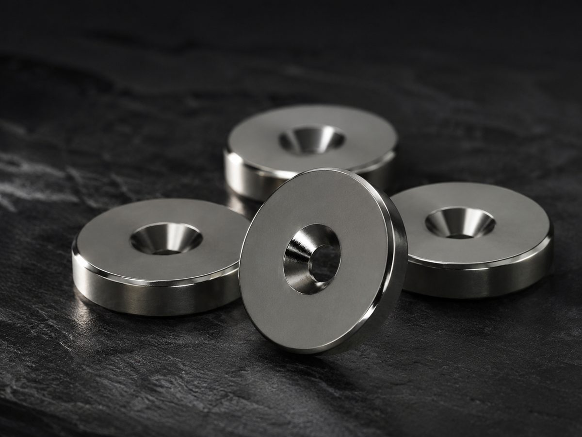
sintered NdFeB
Countersunk Magnets
Sintered NdFeB with a conical bore for flush screw mounting
A countersunk magnet is a sintered NdFeB disc or block machined with a through-hole and a conical seat so a flat-head screw sits flush with, or below, the pole face. Choose it when the magnet must be mechanically retained rather than bonded — vibration, elevated temperature, or a service life longer than the adhesive's. Accept in exchange a meaningful loss of pull force relative to a solid magnet of the same outline, and a bore that must be coated as carefully as the outside faces.
Request a quoteSpecification
- Grades
- N35–N52 in the standard (N) series; M, H, SH, UH, EH temperature variants (e.g. N42SH, N38UH). Note the high-coercivity variants do not span the full range — roughly N45SH, N42UH and N38–N42EH are the practical ceilings
- BHmax
- 263–415 kJ/m³ (33–52 MGOe) depending on grade; high-coercivity variants sit at the lower end
- Max operating temperature
- 80 °C (N) to 200 °C (EH), with M ~100 °C, H ~120 °C, SH ~150 °C, UH ~180 °C — a guide only; the true limit is set by the permeance coefficient of the assembled circuit, not grade alone
- Dimensional tolerance
- ±0.05 mm typical on ground faces (±0.02 mm achievable); wire-EDM features similar at ±0.02–0.05 mm. As-sintered surfaces are much looser — ±0.1–0.2 mm, or about ±1% of dimension. Tighter on request, at cost
- Countersink geometry
- 90° included angle standard (DIN 7991 / ISO 10642 socket head); 82° for Imperial UNC/UNF flat head (ASME B18.3 / B18.6.3). Specify which — they are not interchangeable
- Coatings
- NiCuNi (standard, ~10–20 µm total), Zn, epoxy over NiCuNi, Everlube and other dry-film finishes. Bore and countersink are included in the plated area
- Size range
- Ø8–Ø60 mm discs, 3–15 mm thick, for M3–M8 screws. Practical floor is set by wall thickness, not by the press
- Magnetisation
- Axial (through-thickness) — the pole face is the face you clamp against. Diametral is theoretically possible but rarely offered or useful here
Typical applications
- Removable machine guards, inspection covers and access panels on production equipment
- Jigs and fixtures where the magnet is screwed to an aluminium or steel plate and must not shift under cutting loads
- Signage, display and shopfitting hardware bolted to a substrate rather than glued
- Marine and automotive trim retention where adhesive creep or thermal cycling rules out bonding — subject to a coating specified for the corrosion environment
- Sensor and actuator mounts needing repeatable, serviceable magnet replacement
- Magnetic tool holders and lifting aids where the fastener carries shear and the magnet carries normal load
Engineering notes
- The hole costs you force twice. Removing material from the centre of the pole face — exactly where flux density is highest — typically drops pull by 15–35% versus a solid disc of the same diameter and thickness. Loss tracks the fraction of pole-face AREA the countersink occupies, so a large head in a small disc is the bad case: an M5 head (~Ø9.2 mm) in a Ø25 disc takes ~14% of the face and lands mid-band, while an M8 head in a Ø15 disc will exceed the top of it. Do not size from a solid-magnet chart and subtract a guess; ask for a measured or FEA figure on the actual geometry.
- Wall thickness is the design constraint. Sintered NdFeB is brittle with essentially no ductility: transverse rupture strength is around 250–350 MPa, compressive strength ~1000–1100 MPa, but tensile strength is only ~75–80 MPa — and it is the tensile stress at the cone edge that cracks parts. Leave at least 2 mm of material between the countersink cone and the outer diameter, and at least 1 mm between the cone's small end and the opposite face. Thinner than that and parts chip during plating, handling or screw tightening rather than in service.
- The bore is the corrosion weak point. Standard NiCuNi is electroplated, and electroplating throws poorly into a conical recess and a small through-hole — current density is lowest exactly where you want coverage, so deposit thickness at the cone root can be a fraction of that on the flat faces. (Electroless nickel throws far better but is not the default finish; ask for it if bore coverage is critical.) If the assembly sees humidity, salt or condensation, specify epoxy over NiCuNi and state on the drawing that the bore is a controlled surface; otherwise expect corrosion to start there first. Mind the dimensional sign: plating adds ~10–20 µm per surface, so external diameters and thickness grow by roughly 20–40 µm while the through-hole and countersink SHRINK by the same amount. Size the clearance hole so the plated part still passes the screw.
- Over-torque cracks magnets, not screws. The conical seat concentrates stress at the cone edge, and NdFeB's tensile strength is an order of magnitude below its compressive strength. Use a screw with a matching head angle, seat it against a washer or the substrate where possible, and treat the magnet as a spacer rather than a clamped member. There is no meaningful torque spec — practical values are low, and a torque-limiting driver is worth more than a datasheet number.
- Non-magnetic screws unless you want the field diverted. A steel flat-head screw in the bore acts as a low-reluctance path and will redistribute flux away from the working face. Stainless A2/A4 (austenitic, largely non-magnetic, though cold-worked heads can show slight permeability) is the usual choice; if a magnetic screw is unavoidable, the pull figure from a bare magnet no longer applies and the assembly should be measured as built.
Magnetic properties
Sintered NdFeB grade data
Measured at 20 °C. Every shipment leaves with a hysteresigraph report against these figures — ask for the lot data, not a datasheet reprint.
| Grade | Br (T) | Hcb (kA/m) | Hcj (kA/m) | BHmax (kJ/m³) | BHmax (MGOe) | Max op. temp. |
|---|---|---|---|---|---|---|
| N35 | 1.17–1.22 | ≥ 868 | ≥ 955 | 263–287 | 33–36 | 80 °C |
| N38 | 1.22–1.25 | ≥ 899 | ≥ 955 | 287–310 | 36–39 | 80 °C |
| N42 | 1.28–1.32 | ≥ 923 | ≥ 955 | 318–342 | 40–43 | 80 °C |
| N45 | 1.32–1.38 | ≥ 923 | ≥ 955 | 342–366 | 43–46 | 80 °C |
| N48 | 1.38–1.42 | ≥ 923 | ≥ 876 | 366–390 | 46–49 | 80 °C |
| N52 | 1.43–1.48 | ≥ 876 | ≥ 876 | 398–422 | 50–53 | 80 °C |
| N42M | 1.28–1.32 | ≥ 963 | ≥ 1114 | 318–342 | 40–43 | 100 °C |
| N42H | 1.28–1.32 | ≥ 963 | ≥ 1353 | 318–342 | 40–43 | 120 °C |
| N42SH | 1.28–1.32 | ≥ 979 | ≥ 1592 | 318–342 | 40–43 | 150 °C |
| N38UH | 1.22–1.25 | ≥ 923 | ≥ 1990 | 287–310 | 36–39 | 180 °C |
| N35EH | 1.17–1.22 | ≥ 876 | ≥ 2388 | 263–287 | 33–36 | 200 °C |
Read the suffix, not just the number. None / M / H / SH / UH / EH denote intrinsic coercivity class — higher classes hold their magnetism hotter, at the cost of remanence and heavy rare earth (Dy/Tb). Max operating temperatures assume a permeance coefficient near 2: a thin magnet, or one facing an opposing coil field, will lose output well below the figure quoted. Figures are typical production ranges, not guaranteed minima for every lot.
Answers
Countersunk Magnets FAQ
How much pull force do I actually lose compared with a plain disc?
Typically 15–35% for common disc/screw combinations. It scales with how much of the POLE-FACE AREA the countersink occupies, not with the volume of material removed. A large countersink in a small disc can exceed 40%; a small screw in a large disc sits at the bottom of the band. The honest answer for a specific part comes from a measurement or an FEA run on your geometry — send the drawing and screw size and we can quote a figure rather than a range.
Can you drill or countersink a magnet I already have, or a standard stock part?
No, not sensibly. Sintered NdFeB blanks are machined AFTER sintering, with diamond tooling and coolant, and before magnetisation and plating — the pressed 'green' compact is far too fragile to machine. Cutting into a finished, magnetised, plated part breaks the coating, generates fine swarf that is pyrophoric, and usually cracks the piece. Countersunk parts are made as countersunk parts from the start — plan the hole into the RFQ.
Do I need to specify the countersink angle, or is there a default?
Specify it. 90° is standard for metric DIN 7991 / ISO 10642 socket flat-head screws and is what we cut unless told otherwise; 82° is the Imperial convention for UNC/UNF flat heads (ASME B18.3 / B18.6.3). Mismatching the angle means the head bears on a line contact instead of over the full cone — a concentrated tensile stress on a brittle material, and a common source of field cracking. State the screw standard and the clearance you want on the through-hole, and remember the plated bore ends up ~20–40 µm smaller than the machined one.
Next